This post is a work in progress – it will be expanded and enhanced as the project proceeds.
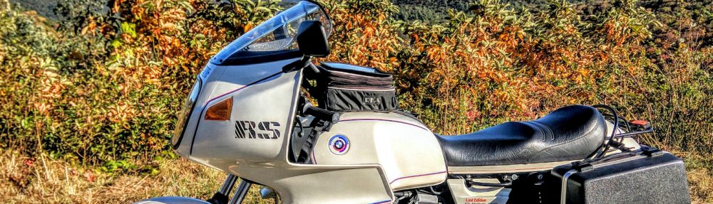
I’ve owned this 1984 BMW R100RS about 3 years now – and put about 10,000 miles on it – the odometer now reads 45,000 miles. In that time the charging system has never failed to keep the battery charged – both a flooded cell and later a AGM.
I owned this same year and model bike, a “Last Edition” back in the 1980’s – I bought one new. That bike had 2 or 3 diode board failures due to solder melting out of the board.
This “new to me” bike has so far had no electrical system failures while I’ve owned it. It does however have two indications of possible electrical faults – 1) The instrument panel voltmeter doesn’t go to a lower voltage in cruise – indicating that the voltage regulator isn’t correctly responding to the battery being fully charged. 2) The instrument panel voltmeter swings widely when operating the turn signals – indicating any number of possible faults. Getting the charging system up to snuff reduces the possibilities and may make tracking that fault easier.
 Dismantling the charging system components I discovered this bike had been modified by the addition of two home-made metal diode board mounts installed on the upper mounts. (The bottom two mounts were original rubber mounts.) The bike appeared to have an original or very old diode board, and had neither the original two diode board grounding wires, nor the addition of the “spider wire” grounding wire advised by Service Information Bulletin 12-019-93 (2611).
Proper diode board grounding is an essential part of preventing diode board failure. As such, the home-made metal mounts on my bike appear to have done a fair job of grounding the diode board to the timing chain chest cover. Presumably, the timing chain chest cover has fair grounding to the engine itself.
After some effort getting up to speed on airhead charging system problem and remedies, I’ve settled on the following plan:
- Replace the diode board with a new OEM part.
- Replace the voltage regulator with a new OEM part.
- Replace the alternator brushes. (entire holder assembly)
- Replace the wires attached to the diode board and alternator not part of the motorcycles main wiring harness.
- Install the two original diode board ground wires.
- Install the additional diode board ground wires. (spider wire)
- Install four new OEM rubber diode board mounts.
Most opinions voiced among the airhead community advocate the use of aftermarket metal diode board mounts. After seeing the flimsy nature of the OEM diode board grounding wires, I can see why. The OEM grounding wires that I purchased for this job are both poorly made and use light gauge wire. I suspect they are inadequate at grounding the diode board – particularly at periods of peak power output.
The other issue about diode board mounts is heat transfer. I’ve heard of people conducting tests that support the notion that metal mounts transfer heat away from the diode board to the timing chain chest cover. I’ve not however reviewed any data confirming these tests. My gut instinct is that a properly grounded and connected diode board operates at a lower temperature than the timing chain chest cover in operation. As such, the OEM rubber diode board mounts would provide some amount of insulation of heat transfer from the engine to the diode board.
Adding to this gut feeling is that after numerous Service Information Bulletins to fix problems with diode board failures, BMW never advised using metal mounts on my particular model – as used on some other airhead models. I’ve not read or heard anything other than conjecture about why BMW never advised changing diode board mounts for my bike.
It’s been noted that rubber mounts will eventual fail due to age. I agree that metal mounts are immune to this problem – but the two rubber mounts on my bike are in in good shape, and may be original to the bike – 30 years old. Replacing them now ought to provide good service for my remaining riding years.
The photo below shows the parts I’ve assembled for this project:
 Examining the two OEM ground wires (shown below the diode board in the photo above) I discovered that the ring terminals were poorly crimped, and made with surprisingly light gauge wire. I decided to make replacement ground wires using heavier (14 AWG) wire and solid brass ring terminals.
This photo below shows a close up of the two OEM ground wires and the first of the two I’ve made to replace them.

I’m considering upgrading the 4-terminal “spider wire” in a similar way.
To be continued…
Thanks for posting these articles. And your list of vendors, even if Stoner and Cutter et al didn’t make it! 8P
RB
Nor Cal
’83 R100RS